Monday, February 13, 2023

How to Capture and Analyze packets with the tcpdump command on Docker Containers  


Docker Containers are running on top of Linux so we have more flexibility in capturing the packets that are exchanged between the docker containers.

Containerlab at the end of a lab deployment reports that it created the containers with the names

Capturing the packets from an interface requires having that interface name and its network namespace (netns)


We use the netns command  to identify the IP links associated with them and capture the packet for further analysis


Using netns command we got the namespace of the container and use namespace and check the link associated with that container in specific 

Use tcpdump command to capture the packet coming to e1 for analysis


Command-List:

ip netns
ip netns <namespace> ip link
Local Capture ip netns exec $lab_node_name tcpdump -nni $if_name Remote Capture ssh $containerlab_host_address "ip netns exec $lab_node_name tcpdump -nni $if_name"


Video Link#


Sunday, February 12, 2023

 How to Install EVE-NG on Laptop Up and Running


Prerequisites for Installation of EVE NG on laptop 

1. Download VMworkstation Player or Oracle Virtual box 

https://www.vmware.com/au/products/workstation-pro/workstation-pro-evaluation.html

https://www.virtualbox.org/wiki/Downloads


2. After successful installation of the VM manager download the EVE-NG OVA image

https://www.eve-ng.net/index.php/download/

3. Upload the EVE-NG OVA Image using VM Player (Click pen a Virtual Machine)


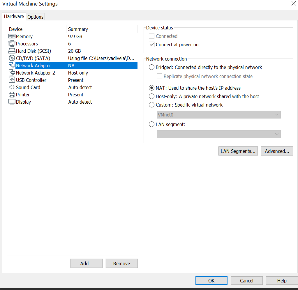
4. Change the VM setting to NAT or VMNET8 


5. Start the VM and login to the Eve-ng VM, during the first time login will prompt with hostname and password to configure

default hostname # eve

default username # root

default password # eve

6. Get the IP address from the VM and use the IP address to access your eve-ng


default username # admin

default password # eve

7. Create your own LAB and start your practice into the master in networking


How to add Cisco IOU Image on Eve-ng Up and Running


Step 1#

Download Linux L2/L3 adventerprise Image 

Step 2#

Upload the downloaded image to the EVE path /opt/unetlab/addons/iol/bin/ using WinSCP or Filezilla

Step 3#

Fix the permission for the added image using the below command

/opt/unetlab/wrappers/unl_wrapper -a fixpermissions

Step 4#

Create an iou keygen file Copy the Cisco IOU Image Script provided below and add to the script

vim /opt/unetlab/addons/iol/bin/ioukeygen.py

Esc:wq

Step 5#

Fix the permission for the Python script

chmod –x vim /opt/unetlab/addons/iol/bin/ioukeygen.py

Step 6#

Run the license generator script 

/opt/unetlab/addons/iol/bin/ioukeygen.py

copy the license generated by the script


Step 7#

Create iourc license file for your EVE
vim /opt/unetlab/addons/iol/bin/iourc

Paste the output captured in Step 6

Step 8#

Fix the permission and start practicing your lab by adding the image on eve-ng web

/opt/unetlab/wrappers/unl_wrapper -a fixpermissions

Cisco IOU Image Script#

#! /usr/bin/python3

print("*********************************************************************")

print("Cisco IOU License Generator - Kal 2011, python port of 2006 C version")

import os

import socket

import hashlib

import struct

# get the host id and host name to calculate the hostkey

hostid=os.popen("hostid").read().strip()

hostname = socket.gethostname()

ioukey=int(hostid,16)

for x in hostname:

 ioukey = ioukey + ord(x)

print("hostid=" + hostid +", hostname="+ hostname + ", ioukey=" + hex(ioukey)[2:])

# create the license using md5sum

iouPad1 = b'\x4B\x58\x21\x81\x56\x7B\x0D\xF3\x21\x43\x9B\x7E\xAC\x1D\xE6\x8A'

iouPad2 = b'\x80' + 39*b'\0'

md5input=iouPad1 + iouPad2 + struct.pack('!i', ioukey) + iouPad1

iouLicense=hashlib.md5(md5input).hexdigest()[:16]


print("\nAdd the following text to ~/.iourc:")

print("[license]\n" + hostname + " = " + iouLicense + ";\n")

with open("iourc.txt", "wt") as out_file:

   out_file.write("[license]\n" + hostname + " = " + iouLicense + ";\n")

print("^^^^^^^^^^^^^^^^^^^^^^^^^^^^^^^\nAlready copy to the file iourc.txt\n ")


print("You can disable the phone home feature with something like:")

print(" echo '127.0.0.127 xml.cisco.com' >> /etc/hosts\n")

# end of the script

Final output on eve-ng


Refer to the video with the steps


Wednesday, January 6, 2021

Configuration of the epipe/l2circuit on the Nokia 7750 SR/7250 IXR

Epipe Configuration on Nokia 7750 SR

This article explains how to configure epipe between Nokia SR routers.

The Cisco term is referred to as xconnect and the juniper term is L2circuit.

Basic Theories:

Epipe name itself identifies it's a point-to-point connection that uses Ethernet encapsulation to pass data bits/bytes between two endpoints. Service provider core act as a layer 2 switch for customer traffic. In other words, this helps to extend the IP segment of the same subnet shared between 2 different locations.


Topology:


ISIS Level 2 and LDP are preconfigured. let's explore the setup to configure epipe and initiate traffic between the 2 sites.

LDP is used to signal the Service label between end nodes participating in epipe.

Nokia: SAP-MTU and Service MTU play an important role.

To bring up the epipe between 2 end nodes we need to take care of Service-MTU and Sap port MTU.

SAP-port MTU and Service MTU should be the same if the encapsulation is null.

If the encapsulation is dot1q or q-in-q then we need Sap-MTU to be greater than Service-MTU because dot1q adds 4 bytes of vlan and q-in-q adds 8 bytes of vlan to the service.

VC-ID should match between 2 endpoints otherwise epipe will not come up. Always make sure Virtual-Circuit Identifier is the same on both ends.

PE01: 1.0.0.1/32

PE02: 2.0.0.1/32

PE01:

ISIS Adjacency is Up between PE01 and PE02


As mentioned above we are going to use LDP as a transport/Signalling protocol. let's verify LDP status.

First, we need to configure SAP port encapsulation towards Site1 and Site2.

I am not going to configure any encapsulation on the SAP port and leave it as default for this testing.

In Nokia, We need to configure SDP to remote PE system IP to use LDP for signaling service labels.

PE01:

/configure service sdp 1000 create

/configure service sdp 1000 far-end 2.0.0.1 ==> remote PE02 SYSTEM IP

/configure service sdp 1000 ldp

PE02:

/configure service sdp 1000 create

/configure service sdp 1000 far-end 1.0.0.1 ==> remote PE01 SYSTEM IP

/configure service sdp 1000 ldp

We can see that SDP is up between the PE routers and using TLDP signaling.

Before stepping into epipe configuration let's verify the SAP  Port configuration towards the Customer Site.

SAP Port configuration on PE01 and PE02

/configure port 1/1/2 ethernet mode access

/configure port 1/1/2 no shutdown

Now we are good to start the epipe configuration and prerequisites are verified

PE01:

/configure service customer 1000 create

/configure service customer description "nokia-site1"

/configure service epipe 1000 customer 1000 create

/configure service epipe 1000 sap 1/1/2 create

/configure service epipe 1000 spoke-sdp 100:1000 create  ==> 100 is your SDP ID and 1000 is VC-ID

/configure service epipe 1000 no shutdown

PE02

/configure service customer 1000 create

/configure service customer description "nokia-site2"

/configure service epipe 1000 customer 1000 create

/configure service epipe 1000 sap 1/1/2 create

/configure service epipe 1000 spoke-sdp 100:1000 create 

/configure service epipe 1000 no shutdown

The configuration is done on both routers. let's verify the epipe status and pass the traffic between 2 sites to verify end to end Circuit is up.

Local/Remote Service-MTU and VC-ID shared using TLDP between PE routers.

LMTU/RMTU - Local/Remote MTU

VC-ID - 1000

Ingress/Egress Label-524283U/524283S

As per the below output, Service MTU and Service Label are shared between both PE nodes. 

Service-MTU and SAP-MTU are the same because we are not using any encapsulation on SAP Port. Epipe is up and running between PE1 and PE2.


Final Verification using the ping between Sites.

Site1: 192.168.0.1/24

Site2: 192.168.0.2/24


SITE-1# ping router 192.168.1.2 rapid count 10 

PING 192.168.1.2 56 data bytes

!!!!!!!!!!

---- 192.168.1.2 PING Statistics ----

10 packets transmitted, 10 packets received, 0.00% packet loss

round-trip min = 0.084ms, avg = 0.610ms, max = 1.26ms, stddev = 0.323ms


Saturday, December 26, 2020

Nokia 7750 SR BGP Next-Hop-Self (NHS) configuration

In our previous blog, we configured iBGP between Nokia SR Routers. PE01 received routes from CE via eBGP and advertised them to PE02.

Nokia Router (Alcatel-Lucent) BGP configuration Basic

Let's explore the output of PE02 for the prefix 10.10.10.5/32 advertised from CE01.


Prefix 10.10.10.5/32  is available in the BGP table of PE02


as per the below output, the route is not installed in the routing table of PE02. lets us explore the reason for not installing in its routing table of PE02.


From the above Output says that Invalid IGP for the next-hop advertised by the PE01 for the 
prefix 10.10.10.5.

By default when the route is advertised from ebgp it will change the next-hop to its own IP.
but in the case of iBGP, let's apply the policy to change the next-hop.

/configure router bgp group ibgp-internal next-hop-self 

After configuring the next-hop-self command on PE01, Now PE01 advertising its IP as net-hop for the 
prefix 10.1.5.5 and installing it in routing table. 


Friday, December 25, 2020

Nokia Router 7750 SR BGP Basic configuration

Let's explore few concepts of BGP and how to configure it on the Nokia 7750 SR

Border gateway protocol is mainly used by Service Providers to carry the huge routing information between different Autonomous Systems.

It uses the well-known TCP port number 179. BGP uses TCP protocol for authenticating its peer router session.

There are two types of BGP as listed below

1. IBGP (Internal BGP used to share routing information within its own AS)

2. Ebgp (External BGP used to share routing information between 2 different AS)

Let's explore how to configure BGP types as per the below topology. IGP is pre-configured as per topology.


1. IBGP configuration between PE01 to PE02 

Forming IBGP between Router system IP/Loopback address is a best practice for family ipv4.

why are we configuring internal BGP on SYSTEM/LOOPBACK IP?

If we configure the adjacency using the physical interface for the ipv4 family it will lead to failure if that particular interface goes down.

Even if we have an alternate path to reach the router it will not be useful if we configure it in the physical interface once the interface goes down.

PE01:  10.10.10.1
PE02:  10.10.10.2

PE01:

/configure router bgp autonomous 

/configure router bgp group "ibgp-internal"

/configure router bgp group "ibgp-internal" neighbor 10.10.10.2

/configure router bgp group "ibgp-internal" neighbor 10.10.10.2 type internal

/configure router bgp group "ibgp-internal" neighbor 10.10.10.2 peer-as 65001


PE02:

/configure router bgp autonomous 

/configure router bgp group "ibgp-internal"

/configure router bgp group "ibgp-internal" neighbor 10.10.10.1

/configure router bgp group "ibgp-internal" neighbor 10.10.10.1 type internal

/configure router bgp group "ibgp-internal" neighbor 10.10.10.1 peer-as 65001

To bring up the BGP one more configuration is required. Need to configure the autonomous system to bring the session up.

/configure router autonomous-system 65001

Let's verify the BGP output:

PE01# show router BGP summary all 
===================================================================
BGP Summary
===================================================================
Neighbor
Description
ServiceId          AS PktRcvd InQ  Up/Down   State|Rcv/Act/Sent (Addr Family) PktSent OutQ
-------------------------------------------------------------------------------------------------------------------
10.10.10.2
Def. Instance   65001       9    0 00h03m22s 0/0/0 (IPv4)  9    0 
         
-------------------------------------------------------------------------------------------------------------------

By default in Nokia SR, it will form the family IPV4 neighborship if we don't configure any family under the BGP configuration hierarchy.


2. eBGP configuration between PE01 and CE01

External BGP configured between PE01 and CE01 router. CE01 advertise prefixes to PE01 and it propagates it's further to PE02 via pre-configured IBGP session.


PE01:

/configure router bgp group "ebgp-external"

/configure router bgp group "ebgp-external" neighbor 10.1.5.5

/configure router bgp group "ebgp-external" neighbor 10.1.5.5 type external

/configure router bgp group "ebgp-external" neighbor 10.1.5.5 peer-as 65002


CE01:

/configure router bgp group "ebgp-external"

/configure router bgp group "ebgp-external" neighbor 10.1.5.1

/configure router bgp group "ebgp-external" neighbor 10.1.5.1 type external

/configure router bgp group "ebgp-external" neighbor 10.1.5.1 peer-as 65001


CE advertising its system IP to PE01:

CE01# show router BGP summary all 
====================================================================
BGP Summary
====================================================================
Neighbor
Description
ServiceId          AS PktRcvd InQ  Up/Down   State|Rcv/Act/Sent (Addr Family)  PktSent OutQ
------------------------------------------------------------------------------------------------------------------
10.1.5.1
Def. Instance   65001      53    0 00h03m30s 0/0/1 (IPv4) 55    0 
         
------------------------------------------------------------------------------------------------------------------

Routes received on PE01 router from CE:

PE01# show router bgp routes 
=========================================================================
 BGP Router ID:10.10.10.1       AS:65001       Local AS:65001      
=========================================================================
 Legend -
 Status codes  : u - used, s - suppressed, h - history, d - decayed, * - valid
                 l - leaked, x - stale, > - best, b - backup, p - purge
 Origin codes  : i - IGP, e - EGP, ? - incomplete
=========================================================================
BGP IPv4 Routes
=========================================================================
Flag  Network                                            LocalPref   MED
      Nexthop (Router)                                   Path-Id     Label
      As-Path                                                        
-------------------------------------------------------------------------------
u*>i  10.10.10.5/32                                      None        None
      10.1.5.5                                                   None        -
      65002                                                           

-------------------------------------------------------------------------------
Routes : 1
=========================================================================

PE01 receiving the route from its external BGP and advertises it to PE02 via IBGP.

PE01# show router bgp summary all 
=========================================================================BGP Summary
=========================================================================Neighbor
Description
ServiceId          AS PktRcvd InQ  Up/Down   State|Rcv/Act/Sent (Addr Family) PktSent OutQ
------------------------------------------------------------------------------------------------------------------
10.1.5.5
Def. Instance   65002      35    0 00h03m52s 1/1/1 (IPv4) 60    0           
10.10.10.2
Def. Instance   65001      50    0 00h23m30s 0/0/1 (IPv4) 50    0           
-------------------------------------------------------------------------------------------------------------------

From the above output, we can see 10.1.5.5 is receiving a route via external BGP and advertising it back to its iBGP peer of 10.10.10.2 PE02.

In our, Next Post let's analyze the routes on the PE02 router and how it's installing it in the routing table.



Wednesday, December 23, 2020

How to configure SFM/ Card/MDA in Nokia SR 7750/77XX series routers

We going to discuss how to configure and bring up the Nokia chassis for the first-time installation like SFM, IOM/IMM Card, and MDA on Nokia 7750/77XX series router.

SFM Card - Switch Fabric Module which is an internal backplane used to switch traffic between different slots on the router chassis.

IMM -  Integrated Media Module which is your line card with a fixed number of media/ports

IOM - Input/Output Module this type of card we can insert different types of media/ports based on the supported type by each Chassis.

Let us explore how to identify and configure our Nokia SR series routers.

1. First find the SFM Type inserted on the Nokia Router.


as per the output we need to configure SFM5 to bring up the Switch fabric module


A:SR1# configure sfm 1 sfm-type m-sfm5-12

Now SFM is configured let's find the Card Type using the "show card" command 

*A:SR1# configure card 1 card-type "iom3-xp"


Now, we are in the final phase to bring up the ports. check and configure the MDA inserted on the line card.

*A:SR1# configure card 1 mda 1 mda-type "m60-10/100eth-tx"


Now the ports are up and we are ready to configure the ports to serve the purpose.